The MoveIt motion planning framework is an open source software for motion planning, manipulation, 3D perception, kinematics, control and navigation. It is built on top of the Robot Operating System (ROS 2) and altogether, remains the third most popular package in the ROS world.
MoveIt provides an easy-to-use platform for developing advanced robotics applications, evaluating new robot designs, and building integrated robotics products for industrial, commercial, R&D, and other domains. MoveIt 2 is the ROS 2 version of MoveIt.
This is the fourth of a series of articles that describe our learning experience and contributions with the MoveIt 2 and ROS 2 communities. The complete series is listed below:
- why MoveIt 2?
- porting and understanding
moveit_core - first demonstrator in ROS 2, planning to a joint-space goal
- sensorless collision detection with ROS 2 (this article)
In this fourth part we present the demonstration of a sensorless collision detection system for the MARA modular robot using some of the moveit_core submodules of MoveIt 2. The whole system is based in ROS 2 and has been tested using the Dashing Diademata pre-release while leveraging the real-time capabilities that our team is developing as part of the H-ROS communication bus for robots.
Collision detection demonstration
In this demo we show a simple MoveIt 2 program that moves the second joint of MARA between $\pm 90º$ and stops-and-changes the direction when a collision is detected.
Technical background
Collision detection is a pre-requisite for safety certification. This is specially relevant for collaborative robots as detailed in ISO 10218-1. Literature describes different methods to detect a collision for safely operating robots. The selected method for collision detection often depends on different factors such as available sensors, data, costs (expenses), complexity and required sensitivity.
For this demonstration, we will use the Han's Robot Modular Joints from Han's Robot, one of our partners. These hardware modules, each, has its own position, velocity and torque sensor. All these values are available directly in ROS 2 thanks to the H-ROS SoM which is attached to each Modular Joint and ensures deterministic, secure and safe robot communications. Moreover, the SoM allows to detect collisions on each individual joint which further enhances the capabilities of the overall system and reduces the reponse time.
For the software implementation, we will be reusing existing submodules of MoveIt 2. In particular, MoveIt 2 includes a dynamic solver which provides a way to calculate the torque values of each joint based on the kinematic parameters and the model of the robot.
With all these tools and hardware available, we implement a method for collision. In the sections below we explain general concepts about sensorless collision detection (including the importance of friction models) and then, describe the selected method: detection by estimating the external torque at every moment in time (comparing real torque with the estimated one).
Sensorless methods for collision detection
Sensorless collision detection methods consist on estimating external torques applied to the robot. By monitoring the external torque it is possible to detect if the estimated torque corresponds to an undesired collision.
Sensorless methods are typically based on measuring the current of each motor and inferring from it the torque of each joint. Depending on the transmission mechanism used by the motor, friction should be taken into account. The simplest methods use the measured torque of the motors and more complex methods take into account the robot dynamic to achieve more accurate detections.
In this case, a method based on directly estimating the external torque in each joint has been selected. To implement this method it is necessary to have the following points: current measurements of each motor, a friction model of the Harmonic drives, kinematic parameters and a dynamic model of the robot.
Friction model for an Harmonic drive
The first part consists of estimating the torque applied on the joint of each robot. For this purpose we need to know the current supplied to each motor and the friction of the transmission between the motor and the Harmonic drive's in each Han's module. We will start by defining some of these variables.
Motor torque ($\tau_r$): torque applied to the robot by the actuators. An internal calculus transforms motor intensity in torque. To know the ideal (without friction) output torque, motor torque has to be multiplied by the reduction ratio of the Harmonic Drive gear:
$$ \tau_m = n K I $$
where:
$K$ = Current-to-torque gain matrix
$I$= Motor Intensity
$n$ = Reduction ratio of the gear.
Joint torque ($\tau_j$): Elastic torque transmitted through the joint. Indicates the real output torque of the motor and can be defined as:
$$\tau_j = n \tau_m - \tau_f $$
where:
$\tau_m$ = Motor torque
$ \tau_j$= Joint torque
$n$ = Reduction ratio of the Harmonic Drive gear
$\tau_f$ = Frictional torque. Torque dissipated in the actuator to joint transmission.
The friction torque in this case is given by the friction model of the Harmonic drives. To calculate this term we must take into account a static and a dynamic term.
In static, Harmonic Drive systems have the peculiarity that a certain value of torque must be applied to the Harmonic Drive gear to maintain the desired position of the position-controlled robot. It should be a constant value, and its sign depends on the applied torque sign. In movement, the value of the friction mainly depends on velocity and on the applied torque.
Both static and dynamic terms are calculated by characterizing the friction with a set of experiments at different velocities and positions and with a least squares method.
Direct estimation of the external torque
The formulation of this method is based in two main terms: joint torque and dynamic torques (gravity, Coriolis & centrifugal terms and acceleration torque).
The general dynamic equation is defined as:
$$ \tau_e = \tau_j + (M(q)\ddot{q} + C(q, \dot{q}) \dot{q} + g(q)) $$
where:
$\tau_e$ = External Torque vector. It is used as an estimator signal to distinguish a collision
$\tau_j$ = Joint Torque vector applied to each joint of the manipulator
$M(q)$ = Inertia Matrix
$C(q,\dot{q})$ = Matrix containing Coriolis and centrifugal terms
$g(q)$ = Gravity Load Matrix
$q, \dot{q}, \ddot{q}$ = Joint position, velocity and acceleration
As we explained before, $\tau_m$, $q$, $\dot{q}$, $\ddot{q}$ are measured directly in each module and published as ROS 2 topics. By taking into account the Harmonic drive friction we calculate $\tau_j$ which is also exposed as topic. Finally, the only part missing is provided by MoveIt 2 which give us the dynamic model of the robot.
Collision detection using ROS 2 and MoveIt 2:
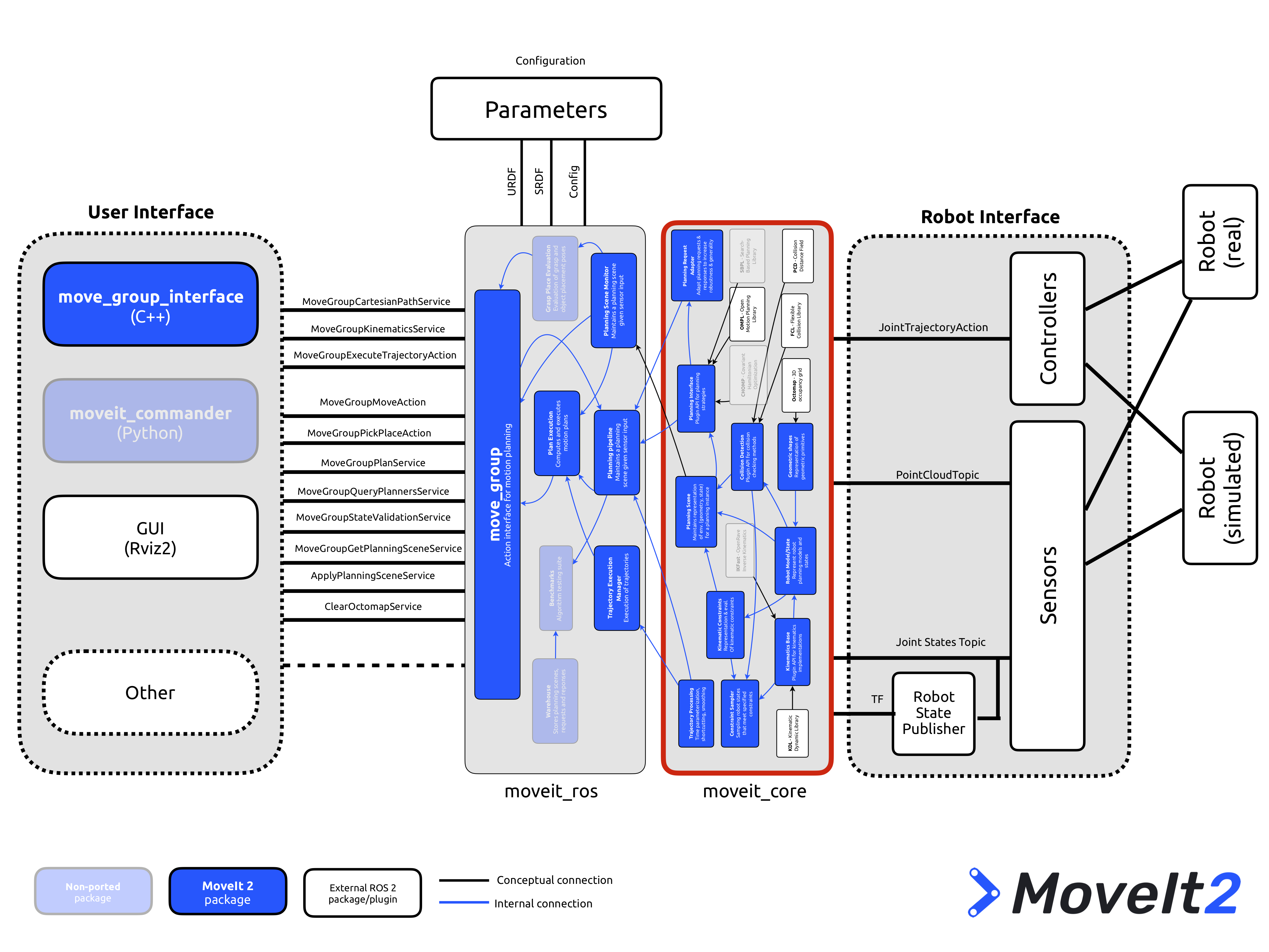
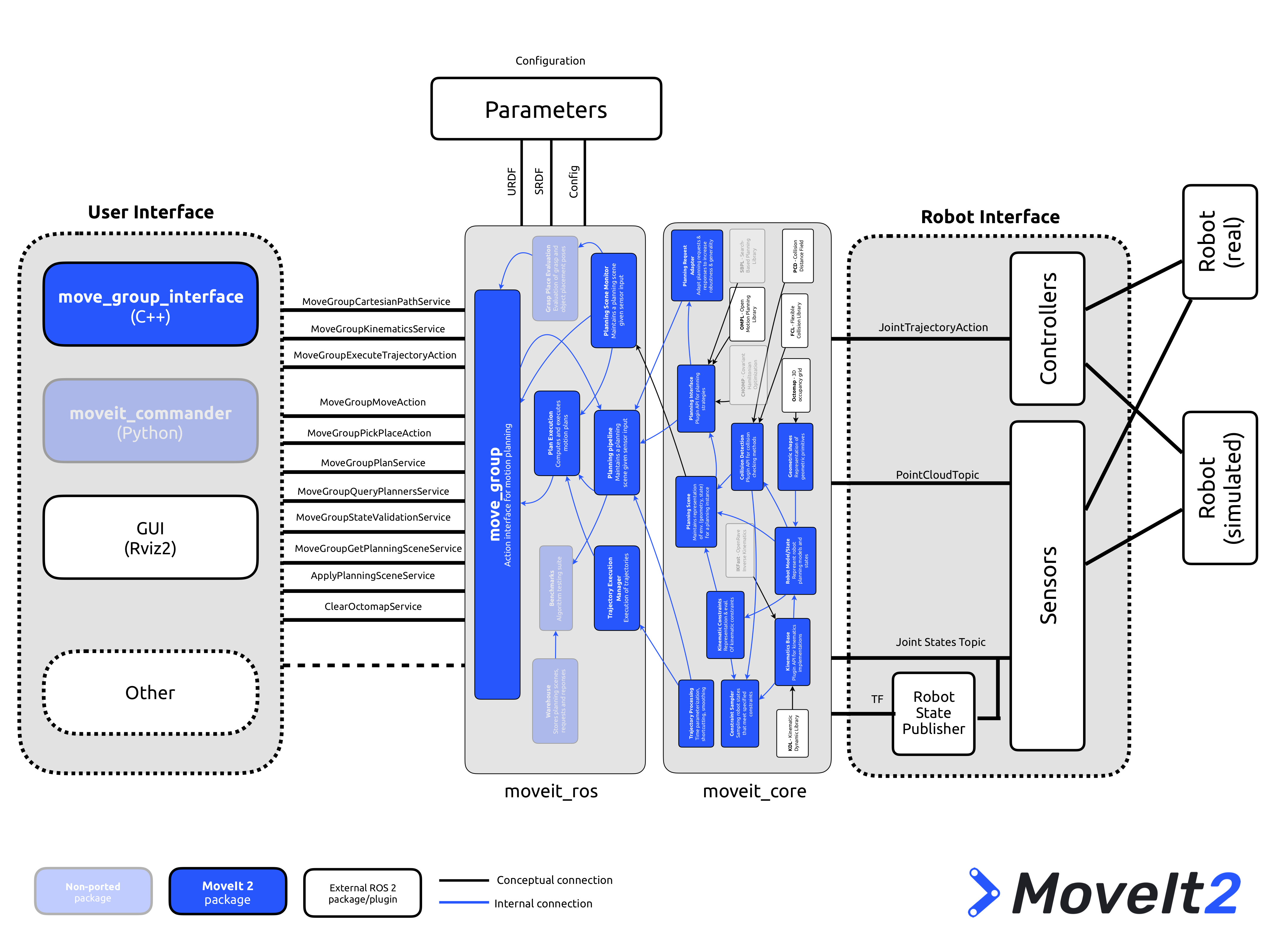
moveit_core, wherein the dynamic_solver module used in this demonstrator lives.To estimate the torque due to the internal status of the robot we make use of the dynamic_solver module inside moveit_core. The dynamic solver calculates the required torques given a joint configuration, velocities, accelerations and external wrenches acting on the links of a robot.
Torques calculated by MoveIt 2 are compared with the joint torques ($\tau_j$). The difference between these torque values can be used to estimate the external torques applied in each joint. Resulting difference signal is used as a collision detection signal. Then, different criteria could be used for collision detection. For example using some filter or based on the change rate. In this example we use a simple threshold criteria; if the signal exceeds a certain value we interpret this as a collision.
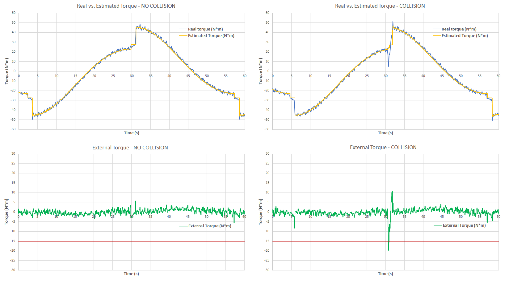
Notice that, as there is noise in the signal due to the velocity and acceleration, and calculations errors, there is a compromise between having false positives and achieving high sensitivity when setting the threshold. In this case we set a threshold in 15 Nm. If the threshold is exceeded, we call the stop command on the MoveIt 2 move_group.
In the plots below we observe a comparison between the joint torque ( $\tau{_j}$ ) and the torque estimated by the MoveIt 2 dynamic model. On the left side we observe the recorded data for a no collision case when moving the joint 2 of the manipulator from -90 to 90º. On the right side we observe the same case but with a collision. When the External Torque ($\tau_e$) exceeds the configured threshold (15Nm) we detect the collision and the robot is stopped.
In conclusion, thanks to the fact that each module provides data such as torque, position, velocity and acceleration, it is pretty straightforward to compute the external torques by using the MoveIt 2 dynamic solver. Also, the real-time capabilities of ROS 2 play an important role here because the collision detection and stop command must be performed under timing constraints. This approach would simplify greatly the deployment of collaborative robots under ROS 2 ecosystem.